Create depended assembly parts using
blocks
Did you ever match a bunch of
holes and shapes at one part with others while making an assembly?

Pic.1
And let add some real design-in-progress
stuff – those holes may eventually changed at the base part and it will require
the changes at all depended parts. How boring and time consuming to change
everything and oops.... some other depended parts will show not appropriate change.
When you see it you probably already spent a while to change almost all
previous depended parts… The fresh idea of changing some design of the base
part may perish just from one thought of changing a dozen parts to fit the
change done on basic part. Along with this manual changes the errors could be
easily done.
So here is idea of tie-up
depended parts by their parameters come up.
There are several ways to make
parts depended from each other, by Excel file, by linking the parameters from
other part or by creating the single IPT file with all necessary parameters
called as Drive Sketch.
Each mentioned way has one time
consuming thing in common. Literally we must create depended stuff from scratch
at every new part using linked parameters taken either from the same Excel or
the same drive sketch or other part. This is quite time consuming way and if
depended holes or special designs are complicated it takes a long and boring
while. This process is also vulnerable for errors.
The other way is create depended
parts using a Derive but this function will force us to create a part in the
same coordinates, other words in absolutely not flexible way.
The one more problem is the
assembly does not have all depended holes same in design. For example you
should match a round bolt hole in one part with round-extended hole in other
part and some other design for a third part as you can see on picture 1.
Depended parts could be absolutely different in overall shape as they are in
real assembly but have dependency in the holes pattern and shape. As you can
see at example at picture 1 the parts #1,#2 and #3 are fit each other but have
different holes shape and different in overall shape.
Making depended parts
Chapter 1. The proposed way is a mix of Drive Sketch and Deriving
technique with using Blocks and it is quite simple. From the beginning let’s talk about an assembly designing from
scratch.
Initially let create a new ipt
file with a single sketch with all necessary holes and shapes which fit each
other as they must correspond and fit each other between depended parts. It
will be the one Drive Sketch for all depended files. As seen from pic. 2 the
round extended holes are correspond to square shaped holes and other bigger
round extended holes are fit for round holes for bolts.
Create a block based on the holes
and shape pattern. This pattern may include the fold-in simple blocks as you
can see on picture. For instance the round extended holes are blocks. In this
way it will be much easier to spread them all over the pattern and make no
errors. Assign a name for this Block to make it easy to find it later.
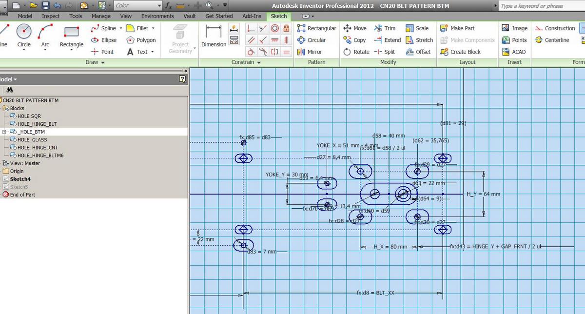
Pic 2
Create or take existing part you
need to be depended and make a Derive of the Drive Sketch file you just
created. Choose the only block(s) you just created, see pic 3. Rule out Sketch
and other stuff you do not need.

Pic 3
Now you are flexible and free in
positioning of this block in this part. You can place it wherever you want not
depending from planes and coordinates. Create a new sketch and place the block
there. Once you make this block fully constrained it will change a color as
fully constrained part. All process of inserting and constraining takes just
few clicks compare to creating the similar pattern using linked parameters, see
picture 4. This linked block is not accessible for editing. It could be changed
only in original Drive Sketch. This block could be mirrored.

Pic 4
As seen from picture 4 the
Sketch23 consisting the only one block derived from Drive Sketch file. Choose
the required holes for this part and cut them. Use
Ctr+Select if you accidentally choose a wrong hole.

Choose and make required holes on
all depended parts, see pictures 5 and 6.

Pic 6
As you can see from pictures 5
and 6 you can choose the required for certain part holes and be sure they will
always fit each other as they fit at the Drive Sketch block. Once changes will
be done to the Drive Sketch block they will affect all depended parts at once.
You can be always sure all depended parts are fit each other after every change
done to single Drive Sketch block. You also can be sure all shapes will be
changed properly at all depended parts.
Chapter 2. This way of making depended parts can tie up some group
of parts depending from one base part(s) dictating the holes pattern or special
shapes or many etc. You will be lucky if holes pattern will be evenly spread
and could be easy duplicated by Pattern tool with exporting just several
parameters.
Mostly
in real assembly holes patterns are not evenly spread and making the same and
depended pattern at other depended part yon can be finally lost in dozens of
tie-up parameters and errors and spend a lot of time

ADVATAGES
·
Easy and vivid way to make depended parts
without big efforts.
·
Any alterations in parameters and depended
shapes are done at same and single Drive Sketch; it is not required to jump
between rows of depended parts to make changes in each file.
·
Much less errors due to “forgetting” to make a
change or wrong change in some depended part.
·
All holes and shapes are visible at same
pattern; this will make less effort changing them correctly and all from one
step. For example we started with M6 bolts and then decided to change them to
M8. All holes and special shapes in depended parts must be changed to other
size. So we see all depended holes at the same sketch and have much less
chances to miss some changes because we clearly see all of them.
·
It resembles the nature way of creating a
puncture stamp and does different parts with exactly the same pattern. Compare
to tie-up parts by linked parameters we can create less errors when we will
change the initial sketch.
·
We can add or deduct additional shapes and holes
in our Drive Sketch and we will instantly have them available at all parts.
Just imagine we decided to set one more fixture and we create some new holes
and corresponded holes at Drive Sketch block and here is a miracle begins. All
we need is to choose fresh holes at our parts and cut them. They are already at
the right place! If we would do it by parameters we should update the linked
file, then choose the new parameters, then create the new hole – at least
several times longer and vulnerable to errors.
·
Easy way to keep some standards on common and
special holes and shapes between all depended parts in assembly since we use
the sole source and do not creating them from scratch at each file.
·
This way also exports the engaged parameters as
long as Derive is used. By editing the derived parts you can also add some more
required parameters from base part without need to make an additional link
between base and depended parts.
Importand.
1.
Make Rebuild All after each Drive Sketch block
change at main assembly or depended parts. Inventor not always automatically
follows all changes made to Drive Sketch block.
Regards,
Orest Yavtushenko, Chief
Designer, Holography Ltd
This article is about easy and sure way of making the depended parts in
the assembly while making a new assembly design. The goal of making depended
parts is changes we will make to one basic part will affect all depended parts
automatically without need to change depended parts manually one by one
No comments:
Post a Comment